How much does a few microns of tolerance actually matter in semiconductor assembly?
In most cases, it’s the difference between a reliable bond and a yield-limiting defect. As bond pad pitches shrink and wire diameters get finer, the dimensional tolerance built into precision tooling has become one of the most direct — and most overlooked — factors determining whether an assembly process holds its accuracy at scale.
Key Takeaways
- Tool tolerance refers to the permitted dimensional variation in a tool’s critical features — hole diameter, tip geometry, overall length — relative to its design specification.
- As bond pad pitch shrinks, tolerance requirements tighten correspondingly: one supplier’s precision capillary holds a 30 ± 1 µm hole diameter to bond 15 µm wire on pitches as small as 35 µm.
- Tight tolerance machining methods — including precision CNC milling, grinding, and ceramic injection moulding — are what make these dimensional specifications achievable in production, not just on a drawing.
- Tolerance errors compound across multiple tooling components in a single process chain, meaning small deviations in several parts can stack into a much larger placement or bond accuracy error.
- Material choice affects tolerance stability over time, not just at the point of manufacture — harder, more dimensionally stable materials resist tolerance drift from repeated wear.
- Specifying tolerance requirements clearly when sourcing tooling is one of the most effective ways to prevent downstream accuracy and yield problems.
What Is Tool Tolerance, and Why Does It Matter So Much Here?
Tool tolerance is the permitted range of dimensional variation a tool is allowed to have around its specified design dimension — for example, a capillary’s hole diameter, a collet’s inner bore, or an ejector pin’s length and straightness. In most mechanical contexts, a tolerance of a few hundredths of a millimetre is negligible.
In semiconductor assembly, where bond pad pitches can run well below 60 microns and wire diameters as fine as 10–15 microns are common, that same margin can be the difference between a successful bond and a failed one.
This is why tolerance specifications in semiconductor tooling are measured in single-digit micron ranges rather than the broader tolerances acceptable in general mechanical manufacturing.
How Tight Tolerances Are Actually Achieved
Meeting micron-level tolerance specifications isn’t a matter of careful hand-finishing — it depends on the precision machining methods used to produce the tool in the first place:
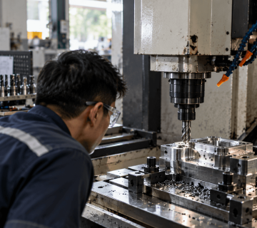
- Precision CNC milling shapes the tool’s base geometry to a tightly controlled dimensional envelope, using rigid machine setups and tooling specifically selected to minimise deflection and thermal drift during cutting.
- Grinding and lapping refine critical surfaces — such as a capillary’s tip or a collet’s bore — beyond what milling alone can achieve, closing in on final tolerance specifications.
- Ceramic injection moulding is used for some bonding tool bodies, offering repeatable dimensional control across high production volumes once the mould itself is qualified to the required tolerance.
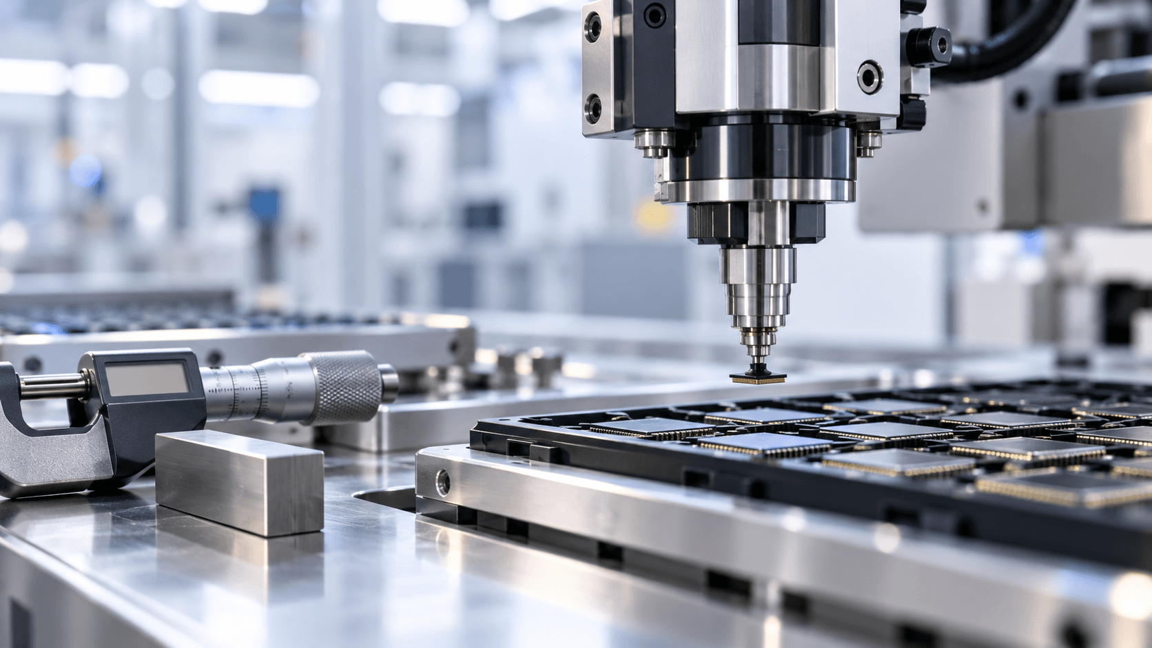
- Dimensional inspection and verification against the design specification confirms each tool meets its tolerance requirement before it leaves production — critical for components where the tolerance band is only a few microns wide.
Each of these steps contributes to the final dimensional accuracy of the tool, and a weakness at any stage can push a tool outside its intended tolerance even if the original design specification was correct.
Why Tolerance Errors Compound Across a Process Chain
A single tool rarely works alone. In a typical die bond or wire bond process, multiple precision components — a pick-up collet, an ejector pin, a capillary, a shear tool — each carry their own tolerance range, and each contributes to the final placement or bond accuracy. When several components are each slightly off from their nominal dimension, those deviations don’t necessarily cancel out; depending on the direction of the error, they can add together into a combined placement error significantly larger than any single component’s individual tolerance.
This is part of why misalignment — one of the most common pick-up and placement defects — often traces back not to a single faulty tool, but to tolerance drift accumulating across several components in the same process chain.
Tolerance vs Material Choice: Why Dimensional Stability Matters Over Time
Achieving a tight tolerance at the point of manufacture is only half the story — the tool also needs to hold that tolerance under repeated use. This is where material selection becomes directly linked to tolerance performance:
| Material | Tolerance Stability Under Wear | Typical Use Case |
|---|---|---|
| Alumina ceramic | High dimensional stability, resists wear-driven drift | Standard bonding capillaries |
| Tungsten carbide | Very high hardness, strong resistance to dimensional change under high-cycle use | High-force, high-cycle pick-up and shear tooling |
| Ruby / Zirconia-toughened alumina (ZTA) | High wear resistance for fine-pitch, high-precision applications | Ultra-fine-pitch bonding capillaries |
A tool manufactured to the correct tolerance but made from a material that wears quickly will drift out of tolerance faster under production conditions — meaning tolerance specification and material selection need to be evaluated together, not as separate decisions.
What Happens When Tolerance Control Fails
Poor tolerance control in precision tooling shows up downstream as familiar production defects:
- Misalignment during die pick-up and placement, as covered in our guide to common pick-up tool problems
- Inconsistent bond strength, since a capillary or wedge tool outside its tolerance range can’t form a consistently shaped bond
- Increased rejection and rework rates, as parts fall outside acceptable placement or bond quality specifications
- Accelerated tool wear, since a tool manufactured at the edge of its tolerance band often has less margin before it drifts out of specification entirely
Each of these consequences ultimately reduces yield — making tolerance control a direct lever on production cost, not just a technical specification on a drawing.
How to Evaluate Tolerance When Sourcing Precision Tooling
- Request the specific tolerance range for critical dimensions — not just a general “high precision” claim
- Confirm what machining and finishing methods (CNC milling, grinding, moulding) are used to achieve the stated tolerance
- Ask how tolerance is verified before a tool ships, and whether inspection data is available
- Evaluate material choice alongside tolerance specification, considering how the tool will perform under your specific cycle count and process conditions
- Consider tolerance stack-up across your full process chain, not just the tolerance of a single tool in isolation
Frequently Asked Questions
How tight does tolerance need to be for fine-pitch wire bonding?
Requirements vary by pitch and wire diameter, but one supplier’s precision capillary design holds a 30 ± 1 µm hole diameter to support 15 µm wire on pitches as small as 35 µm — illustrating how narrow the acceptable tolerance band becomes at fine-pitch scale.
Can a tool be within tolerance when new but drift out of tolerance over time?
Yes — this is why material selection matters as much as the initial manufacturing tolerance. Tools made from less wear-resistant materials can drift out of their original tolerance band well before the end of their expected service life.
Is CNC milling precise enough on its own for semiconductor tooling tolerances?
Precision CNC milling establishes the base geometry, but the tightest semiconductor tooling tolerances typically require additional finishing steps such as grinding or lapping to reach final specification.
Conclusion: Tolerance Is a Production Variable, Not Just a Spec Sheet Number
In semiconductor precision tooling, tolerance isn’t a minor technical detail — it’s a direct driver of placement accuracy, bond quality, and ultimately yield.
Understanding how tolerance is achieved, how it compounds across a process chain, and how material choice affects tolerance stability over time gives manufacturers a much clearer basis for evaluating tooling suppliers.
To discuss tolerance requirements for your specific bonding or die-attach process, Contact Us Now, or explore our tooling for demanding applications in precision tooling for SiC and GaN power semiconductors.