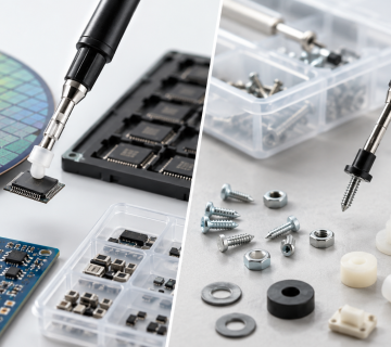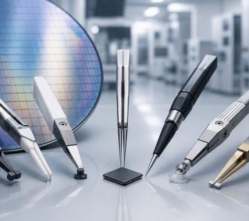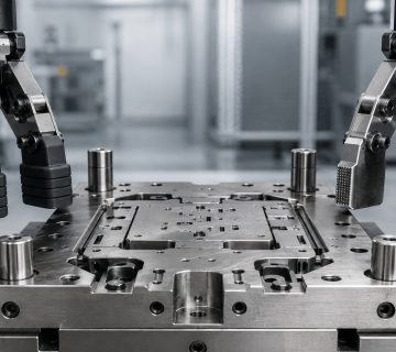
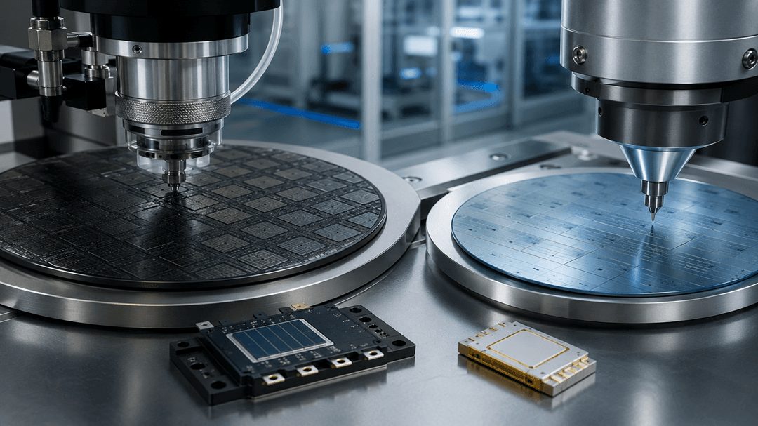
The shift from silicon to wide-bandgap semiconductors—silicon carbide (SiC) and gallium nitride (GaN)—is reshaping power electronics across EVs, renewables, data centres, and industrial systems. For assembly and test operations, this transition goes beyond device design, affecting die geometry, thermal demands, bond pad behaviour, and the precision tooling required for reliable production.
For process engineers and procurement teams, understanding how SiC and GaN alter die bond, wire bond, and QA tooling requirements is critical. Misalignment between material properties and tooling capabilities can lead to yield loss, process instability, and prolonged qualification cycles.
Key Takeaways
- SiC and GaN are wide-bandgap semiconductor materials that outperform silicon in high-voltage, high-temperature, and high-frequency applications — but their physical and electrical properties require corresponding adjustments in assembly tooling.
- SiC semiconductor tooling must account for higher die operating temperatures, different thermal expansion characteristics, and the brittleness of SiC substrates during die attach and handling.
- GaN die bond tools must accommodate the smaller die geometries, higher switching frequencies, and distinct thermal management requirements typical of GaN power devices.
- Both materials drive higher power density designs, which increases the precision and consistency demands placed on ejector pins, pick-up tools, and bonding tooling compared to legacy silicon assembly.
- LeaderRange HiTech engineers custom die bond, wire bond, and QA tooling configurations to support SiC and GaN production lines transitioning from established silicon process tooling.
Why SiC and GaN Are Replacing Silicon in Power Applications
To understand the tooling implications, it helps to start with why these materials are being adopted in the first place.
Silicon has long been the default semiconductor material, but it has a fundamental limitation in power applications: it degrades under sustained high-voltage and high-temperature conditions, constraining the efficiency and power density achievable in silicon-based power devices.
Silicon carbide (SiC) and gallium nitride (GaN) are both wide-bandgap semiconductor materials — meaning the energy gap between their valence and conduction electron bands is significantly larger than silicon’s. This wider band gap allows both materials to withstand higher voltages, operate at higher temperatures, and switch at higher frequencies than silicon, while wasting less energy as heat.
The two materials, however, have distinct strengths that determine where each is applied:
SiC excels in high-voltage, high-power, high-temperature applications. It is the material of choice for electric vehicle traction inverters, on-board chargers, renewable energy systems including solar and wind power conversion, industrial motor drives, and grid infrastructure.
GaN excels in high-frequency switching applications, enabling smaller, lighter power conversion systems. It is increasingly used in consumer electronics power adapters, data centre power supply units, telecom equipment, LED lighting drivers, and increasingly in automotive on-board charging applications where size and weight reduction matter.
Both materials are displacing silicon across an expanding range of applications — and both require assembly process and tooling adaptations that silicon-optimised production lines were not originally designed to handle.
What’s Different About SiC for Die Bond and Assembly Tooling
Higher Operating Temperatures and Thermal Cycling
SiC devices are specifically valued for their ability to operate reliably at significantly higher junction temperatures than silicon — often in excess of 200°C in demanding applications. This has direct implications for die attach material selection and for the tooling used during the die attach process.
Die attach adhesives, solder, or sintered silver materials used with SiC devices must accommodate higher service temperatures, and the assembly tooling — particularly epoxy stamping tools and dispensing equipment — must deliver precise, repeatable dispensing of these higher-temperature-rated die attach materials without degradation in dispensing accuracy.
Die Brittleness and Handling Sensitivity
SiC substrates are mechanically harder and more brittle than silicon. This characteristic increases the sensitivity of the die to mechanical stress during handling, pick-up, and placement — a critical consideration for ejector pin and pick-up tool specification.
Ejector pins and ejector needles used in SiC die bond processes must be carefully specified for tip geometry, force application, and contact area to lift the die cleanly from the wafer or tape without introducing chipping, cracking, or subsurface damage. Where silicon die tolerate a wider range of ejector force and geometry without yield impact, SiC’s brittleness narrows this tolerance considerably — making precision ejector pin specification a more consequential decision than it was for legacy silicon processes.
Rubber pick-up tips must similarly be selected for the correct durometer (hardness) and contact geometry to securely hold the SiC die during transfer to the package substrate without applying localised stress concentrations that could initiate cracking — particularly important given SiC die are frequently used in larger-area, higher-power device formats where uneven pick-up force distribution has a greater impact.
Coefficient of Thermal Expansion Mismatch
SiC’s coefficient of thermal expansion (CTE) differs from silicon’s, and the CTE mismatch between the SiC die, the die attach material, and the package substrate must be carefully managed across the thermal cycling the device will experience in service — particularly relevant for automotive and industrial applications with extended temperature cycling requirements.
While CTE management is primarily a materials and package design consideration, the precision and consistency of the die attach process — governed substantially by tooling accuracy — directly affects how reliably the intended bond line thickness and die attach quality are achieved across production volume.
What’s Different About GaN for Die Bond and Wire Bond Tooling
Smaller Die Geometries and Higher Power Density
GaN power devices are typically manufactured at smaller die sizes than equivalent-rated silicon devices, reflecting GaN’s higher power density characteristics. Smaller die geometries place increased precision demands on die bond tooling — ejector pins must achieve clean, accurate die release from increasingly compact die footprints, and pick-up tooling must maintain secure, stress-free handling at reduced contact areas.
For GaN die bond tools specifically, this often translates to tighter tip dimension tolerances and more carefully engineered geometry compared to legacy tooling configurations developed for larger silicon die.
Higher Switching Frequency and Thermal Management
GaN’s defining advantage — high-frequency switching — generates different thermal behaviour during device operation compared to silicon or SiC devices. While GaN devices generally operate at lower absolute temperatures than SiC in equivalent power applications, the localised heat generation associated with high-frequency switching requires precise thermal interface management at the die attach level.
This places a premium on die attach process consistency — uniform adhesive or solder distribution achieved through accurately specified epoxy stamping tools and dispensing tooling — to ensure consistent thermal performance across every unit in production, not just average performance across a batch.
Wire Bond Considerations for GaN Devices
GaN power devices, like their silicon and SiC counterparts, commonly use wire bonding for die-to-package interconnection. The bond pad metallisation and pad size on GaN devices — often smaller than legacy silicon power device pads, reflecting the smaller overall die geometry — require wire bonding tooling, including EFO electrodes and capillaries, configured for fine-pitch, lower-force bonding to avoid pad damage while still achieving robust, reliable bond strength.
QA tooling — shear pins, shear tools, and wire pull hooks — used to verify bond strength on GaN devices must be appropriately calibrated for the bond strength characteristics typical of these finer-pitch, smaller bond pad configurations, ensuring quality verification accurately reflects actual bond integrity rather than producing false pass or fail results due to tooling mismatch.
Comparing Tooling Considerations: Silicon vs SiC vs GaN
| Consideration | Silicon (Legacy) | SiC | GaN |
| Die brittleness | Standard | Higher — requires gentler ejector/pick-up force | Moderate |
| Typical die size | Larger, established formats | Larger, high-power formats | Smaller, high-density formats |
| Operating temperature | Standard | High (200°C+ junction temps common) | Moderate, frequency-driven thermal profile |
| Bond pad size | Standard | Standard to large | Often smaller, fine-pitch |
| Die attach precision requirement | Standard | High — CTE and high-temp material compatibility | High — thermal interface consistency |
| Ejector pin/pick-up tip specification | Standard tolerance | Tighter — brittleness sensitivity | Tighter — smaller die geometry |
Why Tooling Qualification Matters More for Wide-Bandgap Devices
A recurring theme across both SiC and GaN assembly is that the tolerance for tooling imprecision — adequate for legacy silicon processes — is meaningfully reduced. This is not because wide-bandgap materials are inherently more difficult to handle in an absolute sense, but because:
Die cost is typically higher. SiC and GaN wafers and fabrication processes carry a cost premium over silicon. A yield loss event caused by tooling-induced die damage carries a higher financial cost per failed unit.
Application reliability requirements are often stricter. Many SiC and GaN applications — EV traction inverters, grid infrastructure, industrial drives — operate in demanding, safety-relevant, or long-service-life environments where assembly defects that might be tolerable in a low-criticality silicon device are not acceptable.
Production volumes are scaling rapidly. As SiC and GaN adoption accelerates across automotive, renewable energy, and data centre applications, facilities transitioning production lines from silicon to wide-bandgap materials need tooling qualification processes that catch geometry or force mismatches before they manifest as yield problems at scale — not after.
This combination makes tooling specification review a worthwhile step whenever a production line transitions toward SiC or GaN assembly, rather than assuming existing silicon-qualified tooling will perform equivalently.
How LeaderRange HiTech Supports SiC and GaN Tooling Requirements
LeaderRange HiTech has supplied precision semiconductor tooling — die bond, wire bond, and QA tools — since 2006, and our customisation capability extends directly to the tooling adjustments required for SiC and GaN production transitions.
Our die bond tools range, including ejector pins and ejector needles in standard and hybrid configurations, rubber pick-up tips, carbide tips, and epoxy stamping tools, can be engineered to the tip geometry, force tolerance, and material specifications required for SiC’s brittleness sensitivity or GaN’s smaller die geometries — developed in direct consultation with your process engineering team rather than supplied as generic catalogue substitutes.
Our wire bond tools, including EFO electrodes, support the fine-pitch and lower-force bonding parameters often required for GaN device assembly, while our QA tools — shear pins, shear tools, and wire pull hooks — can be specified to accurately verify bond strength across the different bond pad and bond strength characteristics of silicon, SiC, and GaN devices.
For production facilities running mixed silicon, SiC, and GaN lines — increasingly common as the power semiconductor industry diversifies its material base — having tooling correctly specified for each material configuration, with the customisation turnaround to support rapid qualification, is a meaningful operational advantage during what is often a complex and time-pressured production transition.
Conclusion
SiC and GaN are not simply “better silicon” — they are materials with distinct physical and electrical characteristics that propagate through every stage of the assembly process, including the precision tooling used for die handling, die attach, wire bonding, and quality verification. Production facilities transitioning toward these wide-bandgap materials should treat tooling specification review as a necessary part of that transition, not an afterthought addressed only when yield issues appear.
For tooling specification guidance specific to your SiC or GaN assembly process, contact our engineering team, or explore our full product range covering die bond, wire bond, and QA tooling for semiconductor manufacturing applications.
LeaderRange HiTech Sdn Bhd — ISO 9001:2015 UKAS certified precision semiconductor tooling manufacturer, Penang, Malaysia. Serving 54+ clients across 12+ countries since 2006.